making a hologram printer?

Holography related topics.
gezzer
Posts: 8
Joined: Fri Aug 28, 2015 12:02 pm

making a hologram printer?

Post by gezzer »

okay, this may sound dumb but can we make a hologram printer with a simple 2D CNC machine modified to focus the image on an OLED screen to the small parts of a holographic recording medium one by one?

let's guess we have a printing head moving across the x-y plane made of square OLED screen(or led or etc) with a resolution of 5000x5000 pixels with focusing optics, and a holographic recording medium laying under it.

thinking in terms of simple optics, if we focus the whole screen on a 1x1mm area on the recording medium and have the printing head moving between exposures with 1mm steps, we can transfer an interference pattern from a computer to the medium with 5000 lines/mm resolution.

but i think due to behaviour of light in nano scale, there will be some difficulties focusing the image, i mean beams from the individual pixels will start to interfere each other and will make the projected image on the medium blurred. am i correct?

if yes, how are cgh's printed with methods other than electron lithography? i've read that cgh's can be recorded on holographic mediums using spatial light modulators which afaik simply are lcd screens.
There are a number of ways of making digital holograms in which small regions of the film, termed ‘Voxels’ or ‘Hogels’, are exposed to the pre-calculated fringe pattern, such as by using a spatial light modulator (SLM) or electron beam lithography.
mentioned in:http://holocenter.org/what-is-holography
Din
Posts: 402
Joined: Thu Mar 12, 2015 4:47 pm

Re: making a hologram printer?

Post by Din »

I think you may be confusing several ideas. The problem with phrases like "digital holography" and "computer generated holography" is that these phrases are not precisely defined. Hence, each person has a different concept in mind.

Firstly, digital holography, or digital holograms, usually refers to the fact that the image source is a digital medium, but the hologram is conventional. Basically, in the old Lloyd Cross method, each frame in a video sequence was photographed, then each photograph was back-illuminated (ie light was allowed to pass through it from the back) and some suitable material was added to cause scattering. Thus, an image was created from particular photograph in the video sequence. This image was squeezed into a single line, or slit, by means of lenses, and recorded in the conventional way as a hologram with a ref beam. The plate was then moved by one slit width (or the slit was moved) , the next photograph was brought into place and recorded. So, for example, in The Kiss, you have the woman blowing a kiss at you as she turns. You make a video of it with a movie camera. You place the movie film into a projector and remove the back of the projector. Let's say you want 300 frames across an 8x10in (20x25mm) plate. This means a slit width of either 10/300 in (25/300 mm). So, you run the movie projector, one frame at a time. At each frame, you expose only one slit width of the hologram (~ 0.08mm), then you move the hologram plate (or the slit) by 0.08mm, bring the next frame into the projector and repeat. This is tedious and time-consuming.

Nowadays, instead of a movie camera and a real film, you can set up a video sequence in a computer. The video sequence does not have to be real, it can be a CG sequence of images from MAYA, POSER or any number of 3D image software packages. Instead of threading the movie frames into a projector, you display them on a digital image device, eg an lcd, slm or even your laptop screen (if you can get the back off). The process is then pretty much similar. You create a software package that automates the display of a frame and so bring up the first image of the sequence, shoot it as a slit image, move the slit (or hologram) and shoot the next image. So, for example, the software will do the following (assuming you're moving the plate instead of the slit):
Start with placing all the video frames into a particular folder
Software starts with frame 1 (somehow) and so places frame 1 onto the digital device, let's say an slm
Software waits for settle time (user controlled)
Software opens shutter for a expose time (user controlled)
software moves plate by one slit width (user controlled)
software places frame 2 into slm
Software waits for settle time
repeat.

For example, here's one we made using a similar system, but arranged horizontally, instead of vertically. The image is a CG sequence made from BLENDER https://www.youtube.com/watch?v=zgcKKgQPjuw

This method does not calculate anything. It merely uses a digital image device as the object source and slices the imagery by software.

Now, instead of slicing the images into slits, you can break up the images as a set of square elements, based on view angle. Then, you record each individual square as a square hologram. So, you can break up the image elements into a 300x300 (or even 1000 x 1000) array and record the hologram as a 300 x 300 (or 1000x1000 array). Now, you can pack more information in, and so get parallax in both horizontal and vertical directions. The number of elements per unit distance is the "resolution" of the hologram. However, the spatial frequency of the hologram is not the same as the resolution. This is an often confusing concept. But, you still have not calculated any Fourier transforms. You've broken up the image into a particular geometry. These individual elements are called "hogels". Each one is a hologram in it's own right.
Din
Posts: 402
Joined: Thu Mar 12, 2015 4:47 pm

Re: making a hologram printer?

Post by Din »

For CGH, or Computer Generated Hologram, you actually calculate Fourier terms. Since the far field pattern of any scene is the Fraunhofer diffraction pattern (Note to Petr: Yes, I know you can have Fresnel hologram also! :) ), the fringe pattern recorded on a hologram is the Fraunhogfer diffraction pattern of the object. Thus, instead of actually illuminating an object or transparency with real light, you calculate it's Fraunhofer pattern using an FFT software. You then record the pattern directly onto the plate as a 2-D absorption variation. You can then bleach to convert to a phase hologram.

However, this method requires very large amounts of information and is a long calculation. So, you sample the object wavefront into an N X N array, the sampling interval based on, say, the Shannon theorem. You then record an N x N hologram of each sampled object waveform. The problem is that you have to record both the amplitude and the phase of the FT, ie both the Fourier coefficant and the phase term. There are various ways of extracting this, such as Lee's method ( http://www.ncbi.nlm.nih.gov/pubmed/20216666 ), the kinoform ( http://opticalengineering.spiedigitalli ... id=1221163 ), ROACH, where a three colour process is used. One of the three colours,, the colour you're actually recording with, contains the amlitude information, while the other two colours encode the phase shift.

In all of these methods, you calculate the Fraunhofer pattern with an FFT program, break it up into an array, and record directly onto the medium.Thus, these are Computer Generated Holograms (CGH) because the software generates the data

You don't have to holographically record the phase and amlitude of the FT on a 2-dimensional array. You can convert the FT into a series of height information, let's say white ("1") is 5 microns high and black ("0") is two microns (but you need to encode phase also). Then you can set up a lithography system, such as e-beam, to directly create the surface profile of the hologram, with a certain grey-scale resolution.

Then, there are methods where you generate an image in space from a digital device, but a HOE is used to project the image into free space. One such device is Holoxica (we made the HOE that allows this to work) https://vimeo.com/62616968

This is not a hologram, per se, but it uses holography to create an image in free space.
gezzer
Posts: 8
Joined: Fri Aug 28, 2015 12:02 pm

Re: making a hologram printer?

Post by gezzer »

Hey Din,

What you say is different from what intend to do but i think it's an easier method to record holograms of 3d models from a computer. i think a DLP chip(is actually a slm with moving pixel mirrors on it's surface) or a small lcd slm from a common video projector would work. in case of dlp chip it's a reflective light modulator, for the lcd part it's transmissive. i will just replace its light source with the object beam in a holography setup. So i can make an automated multiplexed hologram printer by the process you mentioned.

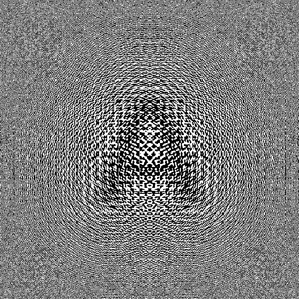
what i actually meant by CGH is this:
Image
this is a computer generated hologram of letter A, you can easily see the calculated fringe patterns. all you have to do is transfer this image to a transmissive surface and you get a hologram. normally best method would be electron lithography but in this case printing on transparency with a common laser printer at 600dpi works. you cannot see a image on the printed transparency but if you point a laser beam through it you can get the image projected. this is due to the limited fringe spacings which could not display the image in visible spectrum, the image projected by a laser beam is very limited in size, i mean diffraction angles are less than a single degree, but it's present, so this is a hologram.

what i want is to print this(actually not this one) calculated fringe pattern in much higher resolution(~125000dpi for 5000lines/mm) so i can get a transmission hologram whose image is in the visible spectrum.

if i can transfer an image in such high resolution, i think i can then calculate a whole hologram like 10cmx10cm, which is hundreds of gigabytes of data for a single hologram, then print it to a holographic plate by splitting it into 1mmx1mm parts.

this response is for your first post, i'll later read your second post throughly and answer. but as far as i understand up to now, i might be missing some ideas about holograms. a hologram is a simple 2d image without any important information recorded in the depth(z axis) of the holographic medium as i know(which i'm not very sure of).
User avatar
admin_jsfisher
Site Admin
Posts: 116
Joined: Sun Jan 04, 2015 12:35 am

Re: making a hologram printer?

Post by admin_jsfisher »

If you have access to a good college library, you may check for this: Introduction to modern digital holography : with MATLAB by Ting-Chung Poon, Jung-Ping Liu.
Din
Posts: 402
Joined: Thu Mar 12, 2015 4:47 pm

Re: making a hologram printer?

Post by Din »

Gezzer,
Yes, that would be a CGH. However, you haven't specified a "reference beam" into the calculation. In this case, you have a "reference beam", that's pretty much on-axis. That is, the reference beam angle is simulated at zero degrees. You need to add the reference beam to get the final spatial frequency. By the way, 5000 l/mm is too high for a transmission hologram, and you can't make a reflection hologram with this method. The spatial frequency of a hologram is given by
lambda*nu = sin(theta)
where lambda is the recording wavelength, nu is the spatial frequency and theta is the interbeam angle. So, let's say you're recording a transmission hologram with 532 (solid state green) at an angle of 60 degrees. Then the spatial frequency is
nu = sin(60)/0.000532 ~ 1628 l/mm

If you want 5000 l/mm, at 60 degrees, you'd have to use light of wavelength
lambda = sin(60)/5000 ~ 1.7 nm!
gezzer wrote:but as far as i understand up to now, i might be missing some ideas about holograms. a hologram is a simple 2d image without any important information recorded in the depth(z axis) of the holographic medium as i know(which i'm not very sure of).
There are two basic types of hologram: transmission and reflection. There are many, many ways of naming a hologram (such as "phase modulated, white light reflection"), but the two types above are the basic types.

A hologram can be recorded as a variation in grey scale with no variation in height. In this method, the light passing through the hologram is modulated by the grey scale variation in absorption. These are called transmission holograms. Since the grey scale variation is caused by two beams - the ref and the object beams - if one of the two beams - the ref beam - is passed through the grey scale variation, then this variation changes the waveform to the other beam - the object beam. Thus the object beam is recovered. Mathematically, the intensity on the film I, with ref R and object O, is:
I = RR* + OO* + R*O + RO*
If this intensity is photographically recorded, the transmission of the film (the grey scale values) is
T = b*i = b(RR* + OO* + RO* + R*O)
If the original ref is now passed through this (2D) structure, then the output is
(R)*(T) = bRRR* + bROO* + bRRO* + bRR*O
You can see that the last term is proportional to the original object beam (bRR*O), the third term (bRRO*) creates a second image, usually called the 'pseudoscopic image". The first term is the zero order term - the non-diffracted part of the ref just passing through the hologram - and the second term is the noise term, unless you record properly, this term creates an aura of light around the image - noise. In this method all light is diffracted, but only the ref wave will recreate the object beam.

Another way of recording the object beam is by means of planes inside the emulsion, like window slats. These "slats" are separated by half the recording wavelength and will only reconstruct with the same ref beam. Any other beam will not reconstruct the hologram. This is known as "Bragg selectivity" because the hologram will select only the ref beam to diffract, no other form of light will diffract. This is not strictly true, but it's a working definition. These are generally called reflection holograms.

Still another way is to modulate the height of the emulsion as a function of the exposure. These are (usually) recorded on photoresist. The end result is a variation or modulation of the surface as a series of varying heights.
lobaz
Posts: 280
Joined: Mon Jan 12, 2015 6:08 am
Location: Pilsen, Czech Republic

Re: making a hologram printer?

Post by lobaz »

Hi, gezzer,
the image you shown is definitely a computer generated hologram (CGH). If you are interested in this subject, you may consider contacting professor Levent Onural at Bilkent University (near Ankara).
There are some algorithms for CGH calculation that are easy to implement. The real problem is how to print them. One solution is, as you mentioned, e-beam lithography, but this is a very expensive way (unless you know some insider that can print you samples in free time). Other possibility is to use optical lithography. It can "print" individual pixels down to size about 0.6 um, which is perfectly OK for display holography. Not cheap as well, but much cheaper than e-beam. For example holograms by Kyoji Matsushima (you can find videos on youtube) are created by an optical litography system built by (I believe) Sumiyo Nakahara.
This is the main reason why CGH is not very popular: very expensive and very slow hardcopy procedure.
Much faster approach does not use CGH, but plain pictures as input and the interference is made optically; Din wrote about this principle in his post. A good resource on this subject is a book by Hans Bjelkhagen and David Brotherton-Ratcliffe "Ultra-realistic Imaging"

Petr
Post Reply