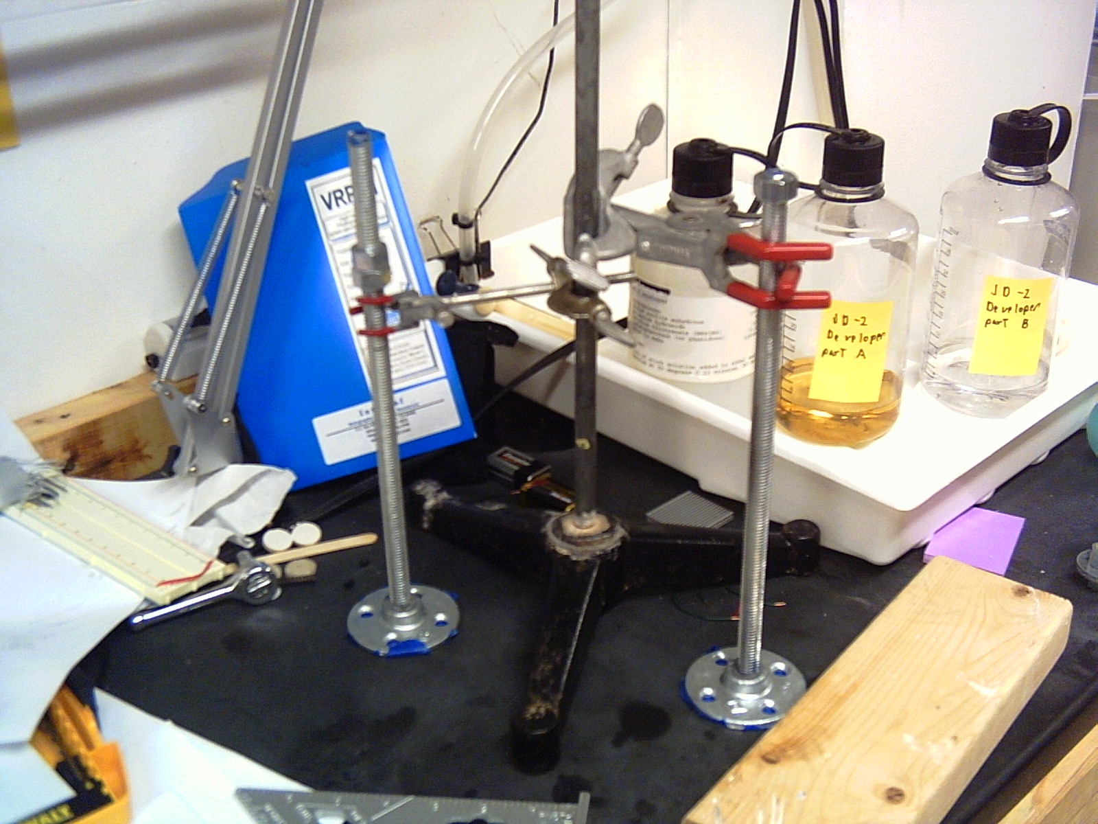
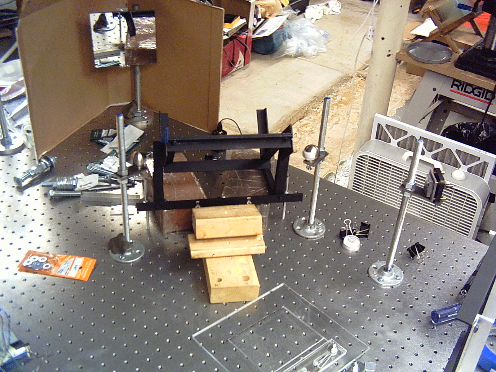
I used JBweld to glue some 1/2 inch threaded rod to some pipe flanges. The flange is then bolted to the table, and the threaded rod goes up vertically.
JBweld is a 2 part metal filled epoxy, you mix the two parts together and it flows easily, a bit more viscous than honey. There is blue masking tape covering the hole in the bottom of the pipe flange. Put some JBweld in the hole, stick the threaded rod in (and mush around to eliminate bubbles), and wait for it to cure. Picture at: http://www.bobdbob.com/~tjohnson/lab/20 ... CT0026.JPG
That is actually the second version of the vertical rods, for my version 3 holography apparatus. My version 2 holography apparatus was a piece of flagstone. I drilled holes in the stone (with a hammer drill), then put threaded rods through it with washers and nuts on either side. Pictures at http://www.bobdbob.com/~tjohnson/stonetable/
To mount optics on the vertical threaded rods, I took pieces of 1/4" by 1" bar stock drilled 1/2 inch holes in one end and 1/4 and #8 holes in the other end to hold various optics. The piece of bar stock is then held on the rod with two nuts, and the optic with another screw on the other end. Picture of a couple and my plate holder at http://www.bobdbob.com/~tjohnson/lab/20 ... ct0024.jpg
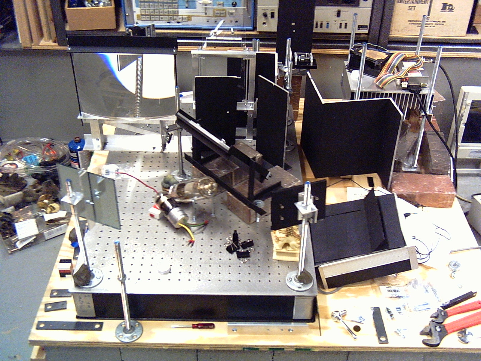
Or for a mirror mount, use a 2 or 3 inch piece of 1" aluminum angle. Drill a 1/2 inch hole on the top on one end, and a #8 threaded hole on the side on the other end. Put a screw in that hole (and tighten it against the threads so it doesn't turn), and use a wing nut to hold a second piece of aluminum angle attached to the back of a mirror. There are two visible on the closest edge of the breadboard at http://www.bobdbob.com/~tjohnson/lab/20 ... ct0003.jpg I attached the mirrors with a couple of small screws and washers, but it could be glued with RTV (which being rubbery, will not put strain on the glass.).
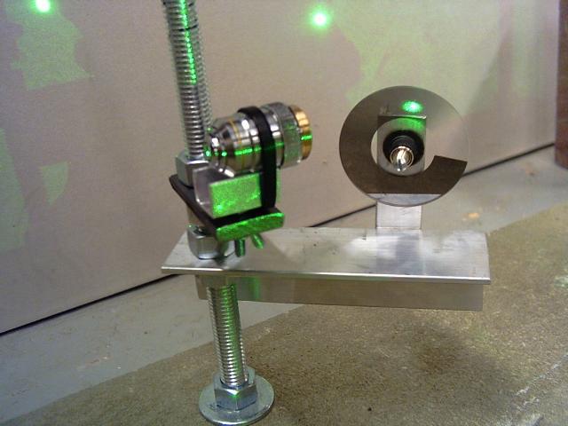
For a microscope objective, get some aluminum U channel (used on the edge of plywood), cut a 1 inch (or so) long piece, drill a hole in the bottom for a #8 screw, and put a nut on it so the piece of U channel is held on the end of the screw. The screw then goes into the #8 hole in the piece of bar stock, with two more nuts above and below the bar (adjust for vertical position). Cable-tie or rubberband the microscope objective onto the top of the U channel so its barrel is supported by the edges of the U. Picture at http://www.bobdbob.com/~tjohnson/stonet ... detail.jpg
"Home Made" holography components
"Home Made" holography components
This is my “test shot mask" i use when making holograms, extremely versatile and easily used, made with only black construction paper and a couple staples...
First I cut a strip 1"x6" film and stick it to my plate holder glass, then I clamp the mask to the plate holder over the film and get it aligned properly. Now start testing
I also use this mask to optimize my ratios!
Holomarks threads were the insentive to post these .............
First I cut a strip 1"x6" film and stick it to my plate holder glass, then I clamp the mask to the plate holder over the film and get it aligned properly. Now start testing
I also use this mask to optimize my ratios!
Holomarks threads were the insentive to post these .............
- Attachments
-
- Test Shot Mask1
-
- Test Shot Mask2
-
MilanKarakas
"Home Made" holography components
Hi, guys.
I made simple solution for automatic delay and exposure time by Canon remote controller (or other device(s) you may have). I already have this controller, so I made very simple flip-flop (two transistor, similar like bistable circuit) and forcing it at one state by adding resistor.
http://www.youtube.com/watch?v=Rybjsj8o6uw
Motor is from small fan for computer use (for small GPU processors, etc.), with removed hall sensor, and connected only three wires instead sensor. One wire is +ve, another two are for two coils, 90 degrees apart - acting as a stepper motor. Not exactly like stepper, it has problem with ring magnet with too big spacing between it and the stator - thus swinging a bit when switched from one to another position, causing stutter interrupt beam during closing once or twice (partially shadowing it during shutting off).
All in all, for my long exposure more than good. I am bad in counting minutes and seconds (sometimes exposing 6 minutes instead 5 or similar miss-counting), so this cheap solution permit me very precise exposure time - excellent for testing holographic exposure for new and unknown formulas.
Black sandpaper blocking the beam.
Paper rotated at 90 degrees, passing beam by.
If someone is interested in messing with, I am willing to provide you additional info 'how to' instruction + circuit diagram.
Best--
m--
P.S. Sorry for cross-posting. I am relative new on the forum, so didn't know where exactly to put this post for DIY-ers. Now I found it.
I made simple solution for automatic delay and exposure time by Canon remote controller (or other device(s) you may have). I already have this controller, so I made very simple flip-flop (two transistor, similar like bistable circuit) and forcing it at one state by adding resistor.
http://www.youtube.com/watch?v=Rybjsj8o6uw
Motor is from small fan for computer use (for small GPU processors, etc.), with removed hall sensor, and connected only three wires instead sensor. One wire is +ve, another two are for two coils, 90 degrees apart - acting as a stepper motor. Not exactly like stepper, it has problem with ring magnet with too big spacing between it and the stator - thus swinging a bit when switched from one to another position, causing stutter interrupt beam during closing once or twice (partially shadowing it during shutting off).
All in all, for my long exposure more than good. I am bad in counting minutes and seconds (sometimes exposing 6 minutes instead 5 or similar miss-counting), so this cheap solution permit me very precise exposure time - excellent for testing holographic exposure for new and unknown formulas.
Black sandpaper blocking the beam.
- Black sandpaper blocking the beam. For high power lasers, consider make two small beam dump plates or cones instead any flammable paper.
- Paper moved 90 degrees, so that beam passes by.
Best--
m--
P.S. Sorry for cross-posting. I am relative new on the forum, so didn't know where exactly to put this post for DIY-ers. Now I found it.
-
zaynah
"Home Made" holography components
this is a very interesting thread.. i wish some more people post and add to this...great work holomaker
"Home Made" holography components
Glad its working for you, and Welcome to the Forum !
-
holowizard
"Home Made" holography components
I'm a relative newcomer to the Forum, but I think I qualify as a veteran holographer...I made my first holograms early in my senior year in high school...1968. I'm guessing I have some of the earliest holograms in existence, outside of the scientific research community. By 1972, I had started what would be a lifetime career as a machinist, and these are some of the things I built to make life easier in the quarter-wavelength-stability world. The beam director was first; all 6061T6 aluminum, 8 1/2 inches tall, 4-inch-square base. Here you see it fitted with 633nm-specific mirrors, but I also used it with 99%+ broadband optics (after I got my first Argon laser). Especially with larger lasers, this turned out to be a must-have accessory. Then, the plateholder...again, 6061T6; this is the 4x5 inch version...I did a 5x7 later when I went to work for the Fleet Space Theater in 1974 (I actually taught a holography class in the basement, but that's another story). This accommodates 1 or 2 1mm thick plates (or a single 2mm plate), so it can also be used for film. The v-grooved delrin plate guides are spring-loaded and ride on ball bearings, and reach immediate mechanical equilibrium...there is no glass-to-metal contact except on the lower edge of the plate. Finally, the spatial filter...patterned after the legendary Data Optics filter, arguably the best SF ever... 2 1/2x4 inch base, 1 inch thick, standing beam entry height, 4 inches. All 6061T6 except for the objective holder and pinhole mount, which are 7075 (to prevent any possibility of galling when the parts are moved against each other). Uses Daedal ball-rail slides, and custom-made 80-pitch drive screws, which give 1.13 microns/degree of screw rotation, making the use of pinholes as small as 10 microns practical. Has a 1/2-inch hole for attaching to an upright post for beam height adjustment (the steel base is 4x1 inch, post, 6 inches, black-oxide finished; crossclamp is black delrin, 1 inch diameter, 2 inches long). There was also an assortment of mirror mounts, etc.
I still have a small machine shop here at the house, and if any member is interested in any of these gadgets, or have any other questions, you can call me direct at (***********)
Phone number edited, please use private message or the email function for contact. Ahmet.
I still have a small machine shop here at the house, and if any member is interested in any of these gadgets, or have any other questions, you can call me direct at (***********)
Phone number edited, please use private message or the email function for contact. Ahmet.

"Home Made" holography components
Welcome to the forums.
Got any pictures of the things you've machined?
Got any pictures of the things you've machined?
World's worst holographer
-
holowizard
"Home Made" holography components
Somehow, I managed to leave out the images in the above post...and now, I'm having a devil of a time posting them...some help?
-
holowizard
-
holowizard
"Home Made" holography components
And, here is the spatial filter...I built this when I had been working as a machinist for only two years, and this works as good as it looks. This unit just celebrated its' 39th birthday...
- Attachments
-
-
-
-